Formity Labs
The Node Layout Algorithm Behind Formity UI
A deep dive into how I designed a recursive layout algorithm to automatically position nodes in complex flowcharts — the foundation of Formity UI’s interactive form builder.
Overview
To streamline the process of building advanced multi-step forms, I created Formity UI — a combination of a UI kit and a form builder. I wanted the form builder to be powered by an interactive flowchart, so I chose to use React Flow, a powerful library for creating node-based editors and interactive diagrams.
However, working with React Flow wasn't entirely straightforward. There were several things I had to implement myself — one of the most important being a node layout algorithm that could automatically position nodes based on their sizes and connections.
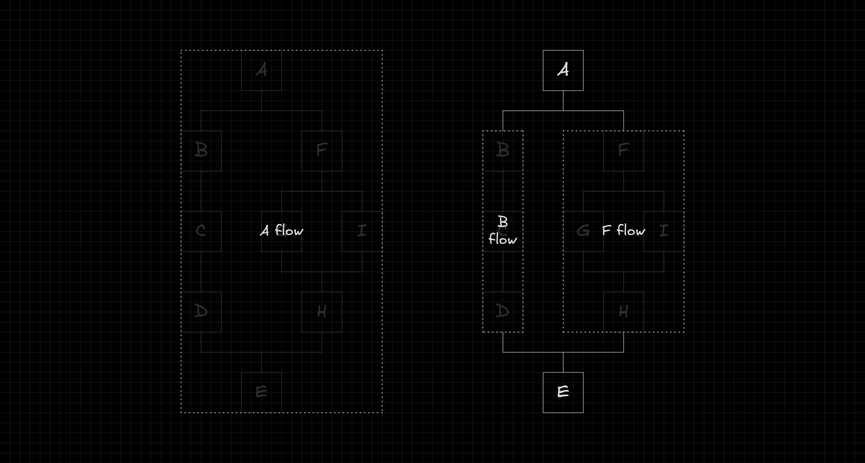
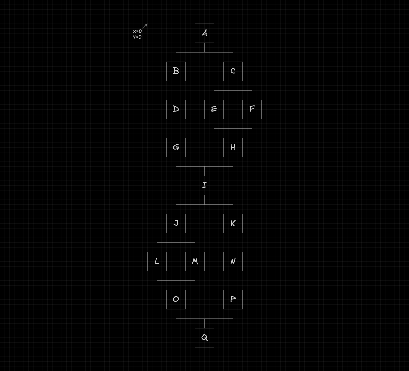
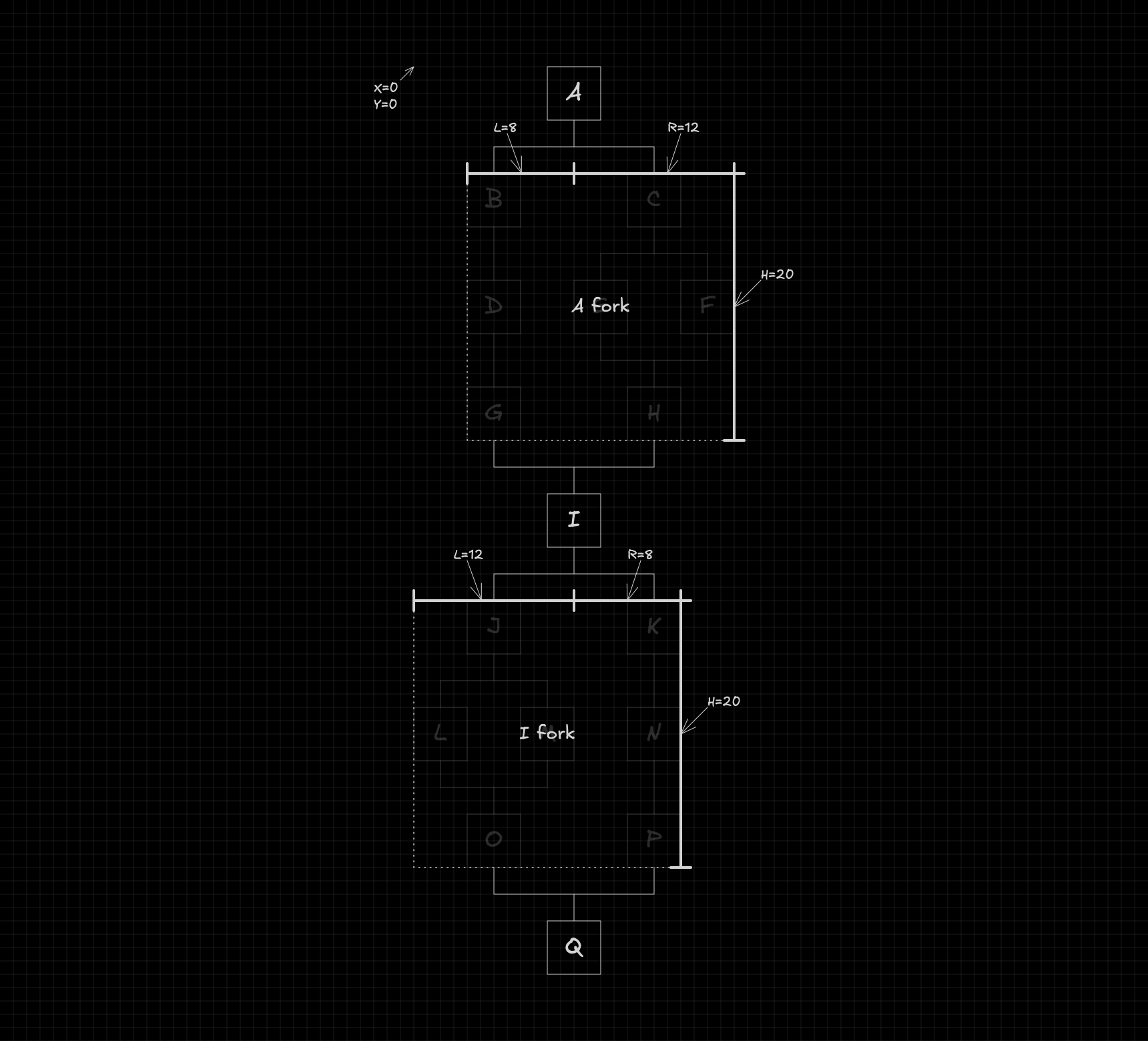
Specifically, I wanted to build a function that could take a flowchart structure like the one below:
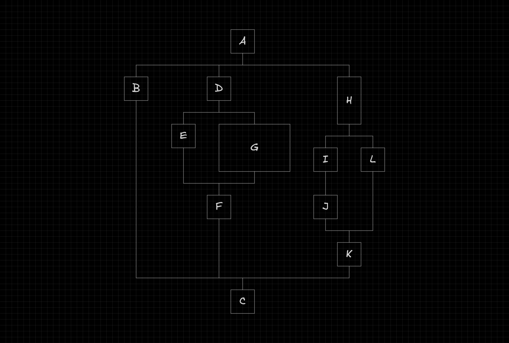
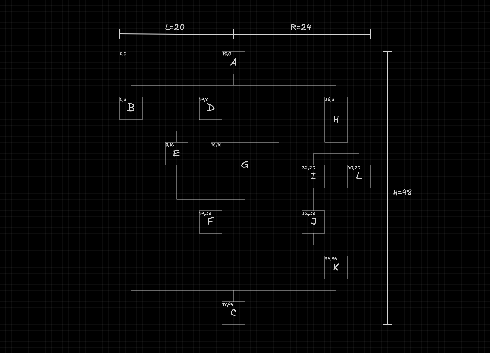
...calculate the position of each node, mutate the original flow with the new coordinates, and return the overall dimensions of the flowchart, as shown here:
In this article, I'll walk you through how I built this layout algorithm and the reasoning behind it. We'll go step by step through the key ideas and constraints that shaped the solution, so you can clearly understand how it works and how everything fits together.
Structure
Before diving into how the algorithm works, we first need to understand how the flowchart is structured.
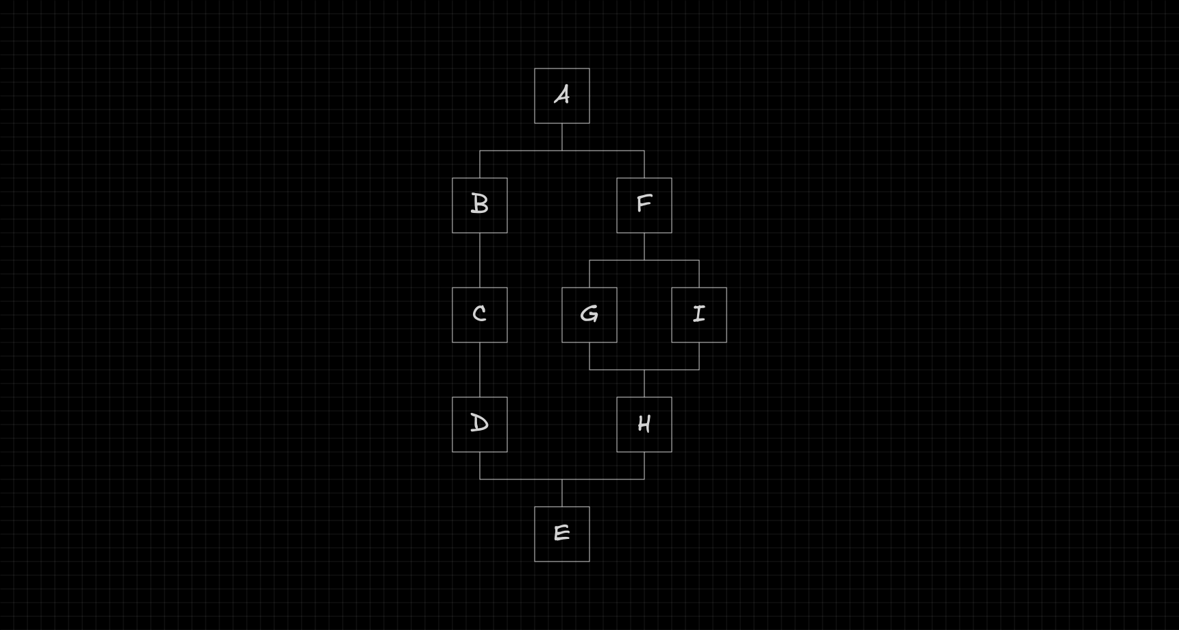
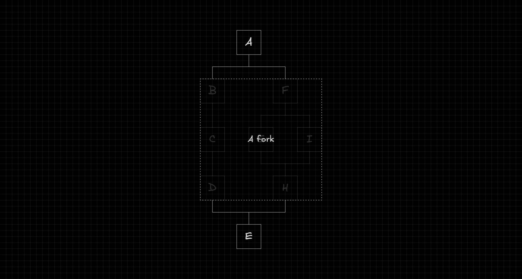
At its most basic level, the flowchart can be seen as a sequence of nodes.

At certain points, a node can create a fork, where the flow branches into multiple paths, with each path acting as a separate flow that eventually merges back into the main one.
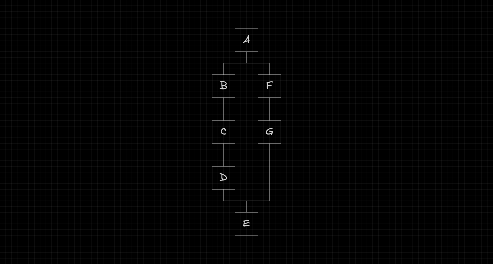
Since each path is itself a flow, it can also create its own fork, forming a recursive structure.
Code representation
To represent this flowchart in code, we define a TypeScript interface describing what a node looks like.
export interface Node {
  id: string;
  position: {
    x: number;
    y: number;
  };
  size: {
    w: number;
    h: number;
  };
  next: Node[];
  prev: Node[];
}
Configuration
To keep the layout flexible, the distance between nodes is controlled by a configurable gap. This gap defines how much horizontal and vertical spacing should be left between each node.
interface Config {
  gap: {
    x: number;
    y: number;
  };
}

export const config: Config = {
  gap: {
    x: 4,
    y: 4,
  },
};
Notation
Before diving into the algorithm, let's define the notation we'll use throughout the explanation.
Node
Each node is represented by a single letter, such as , , or .

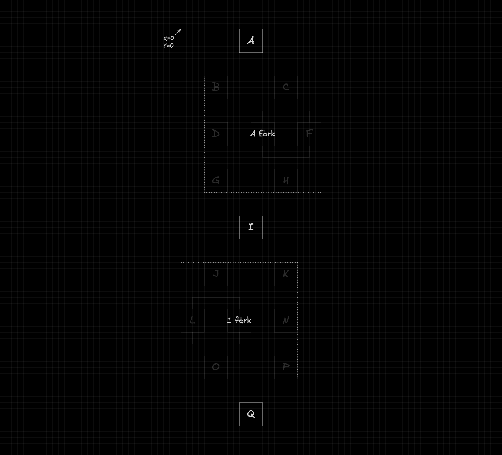
Flow
A flow is identified by the letter of its root node, followed by the word flow.
For example, a flow starting at node is written as .
Fork
A fork is defined by the letter of the node that creates it, followed by the word fork.
For instance, if node creates a fork, we'll refer to it as .
Attributes
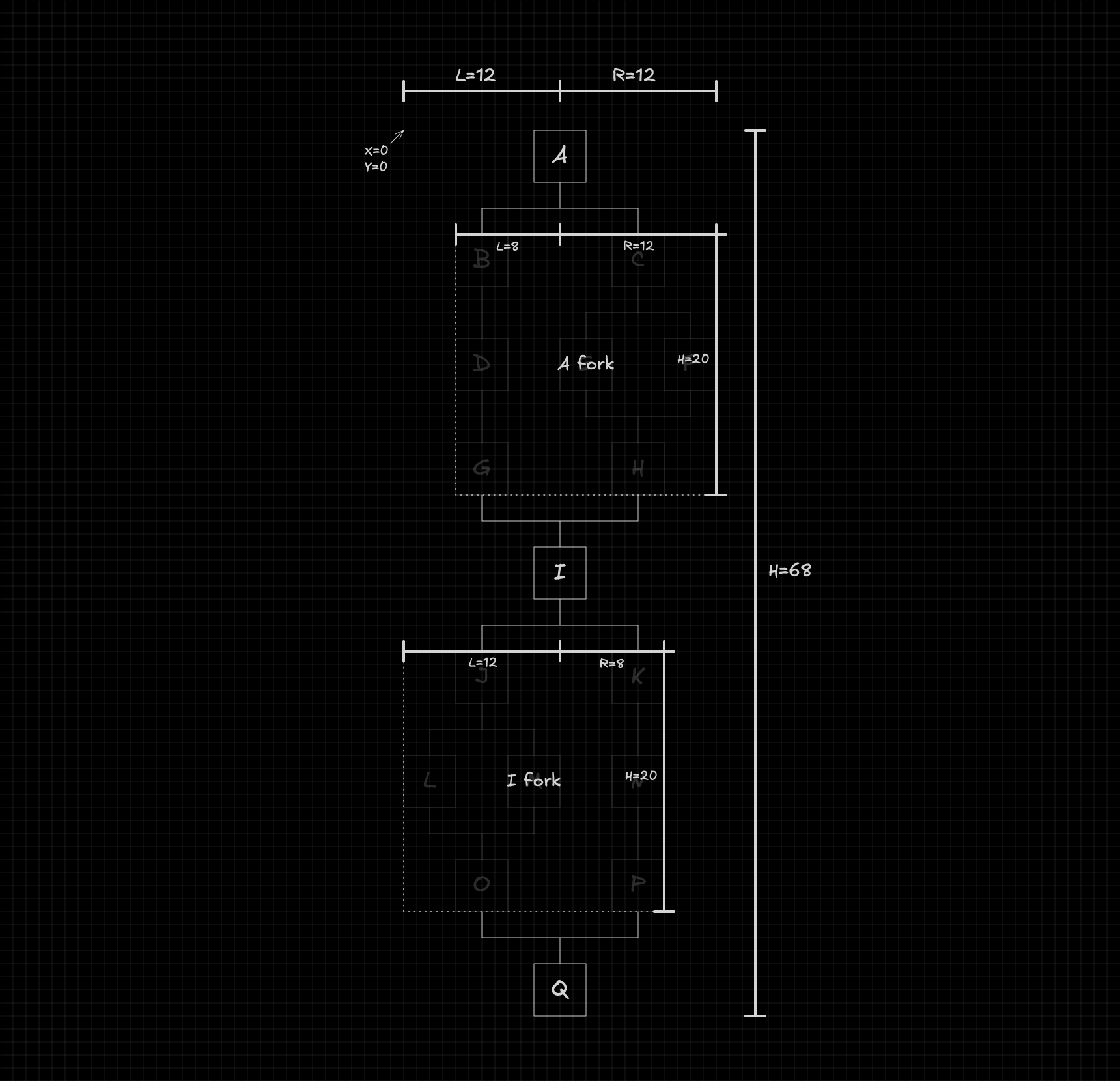
We'll use subscripts to represent the geometric attributes of nodes, flows, and forks.
- : The x-coordinate of node .
- : The y-coordinate of node .
- : The width of node .
- : The height of node .
- : The distance from the left edge of node to the center of the flowchart.
- : The distance from the right edge of node to the center of the flowchart.
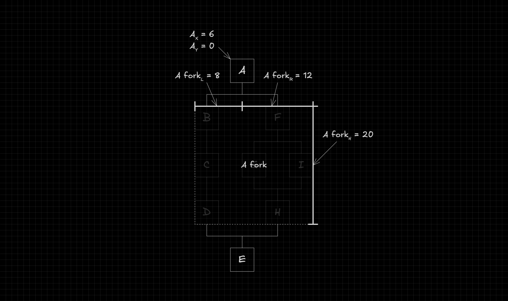
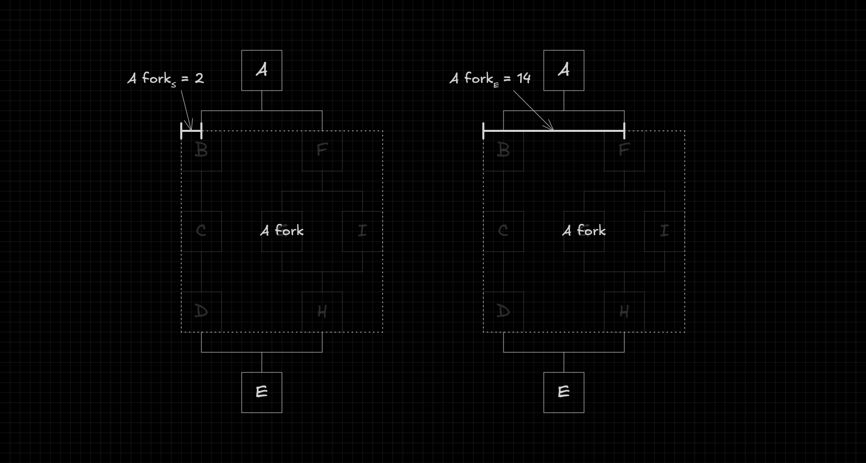
When we're talking about forks, we use two additional attributes:
- : The start of the fork — the distance between its left edge and the center of its first flow.
- : The end of the fork — the distance between its left edge and the center of its last flow.
Algorithm
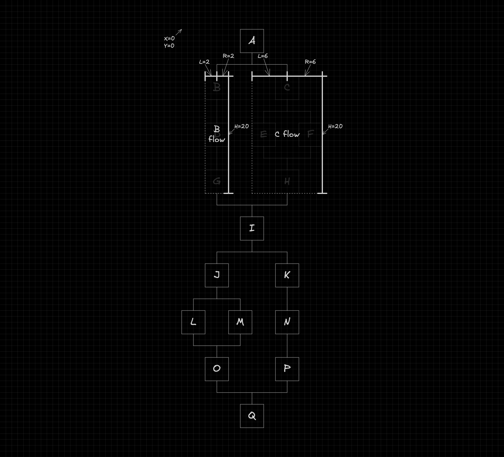
Now that the main concepts are clear, we can start exploring how the algorithm works. Throughout this explanation, we’ll use the example below as our reference.
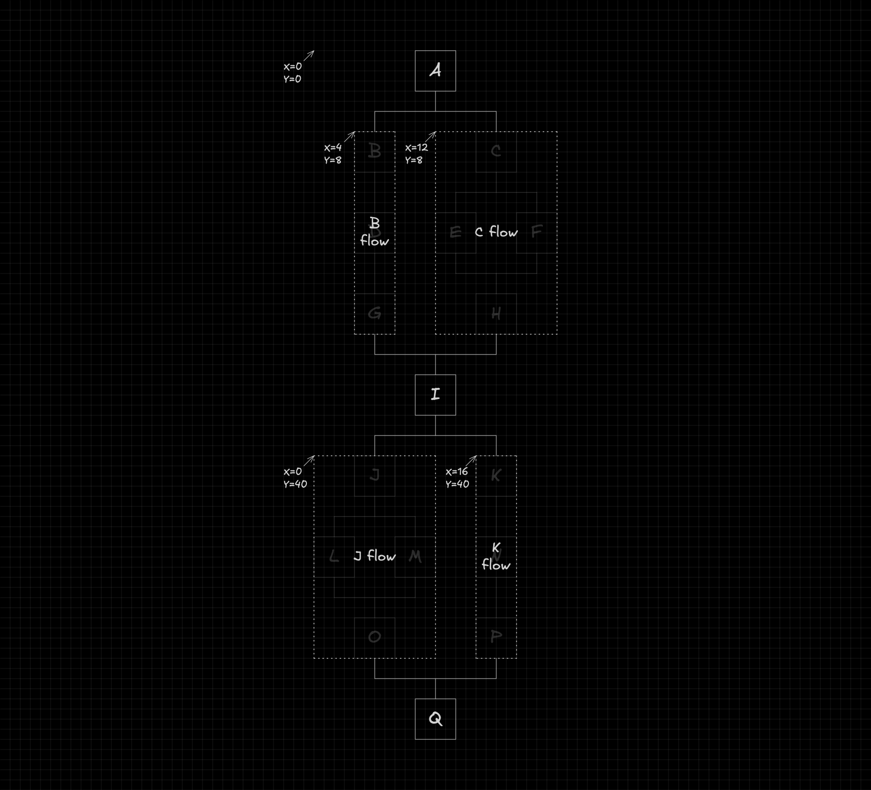
Computing positions
To compute node positions, we can simplify the problem by treating each fork as a single element.
Next, we need to identify what information is required to calculate the positions of the nodes and forks. Specifically, we'll need the dimensions of the flow and each fork, as shown below:
With these dimensions, computing positions becomes straightforward. The calculations are as follows:
The function responsible for computing these positions can be defined as:
function setPositions(
  node: Node,
  position: {
    x: number;
    y: number;
  },
  dimensions: DimensionsFlow,
) {
  // ...
}
The dimensions object contains the dimensions of the flow and its forks, and is defined as shown below:
interface DimensionsFlow {
  flow: {
    l: number;
    r: number;
    h: number;
  };
  forks: Record<string, DimensionsFork>;
}

interface DimensionsFork {
  fork: {
    l: number;
    r: number;
    h: number;
  };
  flows: Record<string, DimensionsFlow>;
}
Finally, the positions of all nested flows within each fork are computed recursively, with a new call made for each flow using its corresponding parameters.
Computing dimensions
Before we can compute the positions, we first need to create the dimensions object. This object can be generated using the following function:
function getDimensionsFlow(node: Node): DimensionsFlow {
  // ...
}
This function internally computes the dimensions of each fork by calling:
function getDimensionsFork(node: Node): DimensionsFork {
  // ...
}
Using the data returned from these forks, it then becomes straightforward to calculate the overall dimensions of the flow with the following formulas:
The getDimensionsFork function, in turn, calls getDimensionsFlow to compute the dimensions of each flow within the fork. Using this information, it calculates the dimensions of the fork as follows:
Final steps
Now that both functions are defined, the final step is to combine them. The function below uses them together to compute the position of each node and return the overall dimensions of the flow.
export function autoLayout(root: Node): { l: number; r: number; h: number } {
  const dimensions = getDimensionsFlow(root);
  setPositions(root, { x: 0, y: 0 }, dimensions);
  return {
    l: dimensions.flow.l,
    r: dimensions.flow.r,
    h: dimensions.flow.h,
  };
}
Complete code
Now that the full reasoning is clear, you can explore the complete implementation on GitHub. It includes every detail discussed above, so you can review or experiment with the code yourself.